By: Jeremy Neisser
The term Noise Temperature has two rather simple yet distinct meanings in the RF community. This article focuses on its use as a measurement of noise power, whereas another post will explore how it relates to wireless link performance.
Conceptually, Noise Temperature is not much different than other temperature scales we are familiar with (Celsius, Fahrenheit).
But unlike these scales which are bounded by absolute zero (-273°C and -459°F), there is no lower limit for noise temperature!
What this means is that if you were to take a thermometer mounted to an antenna you could theoretically measure negative temperatures. It may seem counter-intuitive, but every signal generates some noise which must be accounted for when performing measurements of any kind.
An analogy might be a bucket of water. If you pour too much in, it overflows and makes a mess (or worse). If you don't pour enough in, it remains empty (noise temperature also has a minimum value!).

What does noise temperature mean?
Fundamentally, Noise temperature it is the average noise power density (measured in W/m2) at a particular location.
Like any temperature scale, we can use this value to determine the properties of the noise: specifically its frequency spectrum and amplitude distribution.
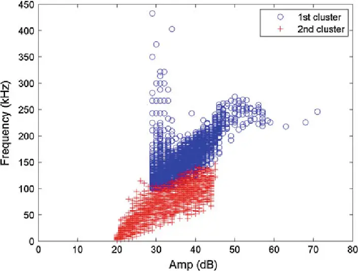
The figure below shows two equally populated distributions of signal power with their respective spectral signatures (blue and red).
If you ever wondered why radio engineers sound so excited when they talk about signals with flat spectrums, imagine how much more exciting they get when talking about signals that are perfectly flat from DC to light!
The signal shown in red has an effective isotropic radiated power (EIRP) equal to 100W; whereas the blue's EIRP is 50W.
Since the noise power is simply given by the product of the signal and the noise temperature, you can see that each has a distinct amount of thermal noise figure nf (both in terms of amplitude and frequency content).

https://www.researchgate.net/figure/Frequency-amplitude-distribution-chart-for-specimen-without-tempering_fig3_257803525

What is noise temperature in communication?
In most RF communication systems, the thermal noise figure is the number 1 limiting factor to system performance.
If you have spent time trying to figure out why a particular system doesn't work as well as expected, it is likely due to having an insufficient amount of the thermal noise figure nf at either your receiver or transmitter!
When discussing this topic with colleagues typically one of two things happens.
Either they get excited and start telling me about how cool their noise source is, or they look confused and tell me "noise temperature? I never heard of that".
This first response usually comes from the antenna community; because without one, you will not be able to make any measurements! The second response (confusion) often stems from microwave engineers who think about power rather than noise; as they are typically using much higher frequencies (GHz vs. GHz).
The next section will provide a succinct yet practical explanation about how noise power and temperature relate to one another when it comes to wireless communications.
How Noise Power Density Relates To Wireless Communications
As was mentioned before, thermal noise is an unavoidable byproduct of all RF systems with the exception of quantum entanglement devices that may exist out in the future!
But for now, if you want to send information across a noisy channel, you must find a way to overcome this problem.
The most straightforward approach: throw more signal at it!
By transmitting your data faster (shorter symbol duration), you will statistically double the amount of useful signal energy compared to using slower signaling (longer symbol duration).
The trade-off with this approach is that you are also increasing the amount of noise power.
In order to compensate for this additional noise, you must use a system with a lower noise temperature than the one used in your first system.
So if your first system had a temperature of -127°C and was not sufficiently noisy, then you might want to try something like a -140°C system instead! This would result in 2x the signal amplitude over the original transmitter/receiver pair.
To put it another way: As the bandwidth parameter increases by an integer factor, the noise power density decreases by an equal but opposite amount.
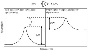
This can be seen visually by the following figure:
Although you might be thinking that this presents a bit of a conundrum, I'm sure you will agree it's not much of one.
For any band from TV channels to aircraft carrier communications links to microwave ovens at 2.45 GHz, there are multiple noise sources!
The human body (you) is a great source of thermal noise and emits roughly -100°C. Other sources include radios, televisions, fluorescent lamps in cubicles and offices, and anything else using electricity or light bulbs!
In summary, here is a list of some common "thermal power" systems that could be used as channel models for wireless experimentation :
-127°C or 30uW/m 2 @ 0.1GHz
1Watt light bulb 3m away -140°C or 600nW/m 2 @ 10GHz
Human body 20cm away -160°C or 40pW/m 2 @ 100MHz
Human body 1m away
Where can noise temperature be found?
How does one measure it?
Noise temperatures are typically specified for devices like mixers, amplifiers, and antennas.
Since these devices typically operate within a few hundred MHz to tens of GHz range, they do not strictly follow the "1/f" rule that thermal sources in the megahertz to gigahertz range do; but we will get into this later!
What is the noise temperature of the LNA?
What is the noise temperature of the antenna?
Why is this important for wireless communications?
Noise Temperature is an extremely helpful parameter in understanding how propagation works. Infrared light (heat) travels much slower than visible or ultraviolet light which in turn travels slower than microwaves or radio waves.
A more interesting fact is that the speed of propagation does not change with frequency, but rather it changes with wavelength :
The most dramatic illustration I can think of relating to this topic would be on a clear sunny day outside during the summer.
If you could look up into space, you would notice that there are no cosmic rays (high energy particles) because they cannot travel through IR radiation.
How is a signal to noise ratio calculated?
The general formula for calculating SNR is:
If we wanted to find the signal power and noise power for a receiver, this would be much easier. First of all, if we know the transmitted symbol duration T, then all we have to do in order to find SINR would be to multiply it by √ Signal Power over Noise Power.
Let's walk through this together using our LNA noise temperatures above:
We used the 4th-order polynomial approximation for determining ΔT from Δλ instead of taking the more complex integral because it was simpler!
This gives us 2Watts of transmitted energy at 10MHz when using an antenna with -140°C noise temperature indicating that that is a clean channel without additive noise.
Our 1Watt light bulb is completely useless as a transmitter, but don't feel bad for the light bulb; it's in the industrial microwave band (2.45GHz) so it can already transmit from room to room and office to office over thousands of feet with no problem at all!
If you're wondering why we didn't use -160°C our human body model or any other thermal power source for transmission, remember that these sources only produce radiation that falls within infrared frequencies; which are not strong enough for propagation.
We are going to rework this equation into:
Note that Δλ=c/f . This gives us: SINR = (4πfΔλ)/(f×√Signal Power over Noise Power) .
If we wanted to find the noise power, it would be very simple; all that we have to do is to multiply -127°C by 2.45GHz since this represents our noise temperature of -200dBW/m2 at 2.45GHz . This gives us -51.52dBm!
The formula for finding Signal-to-Noise Ratio (SNR):
Is SNR a useful parameter? Can you use it for anything?
Yes, definitely! Most applications function with a certain level of error which can be translated into an acceptable signal strength based on the user's needs and
You May Like: How Far Do CB Radios Work
What is a good noise figure? What's a bad noise figure?
The best that you can have is 0dB which means that your device produces the same amount of noise as it receives. In this case, we would say that our system has a Noise Figure of 0 dB in decibels.
This isn't always possible because there must be some loss within the system.
As long as the loss doesn't exceed 6dB (the maximum Gaussian Error Factor), then we are OK!
Here is the updated chart:

https://electronics.stackexchange.com/questions/293933/why-is-a-lower-noise-figure-considered-better-than-a-higher-noise-figure
Look at what happens when you get closer to 2GHz and all the way up until 11GHz!
Now everyone knows why cell phone companies offer smartphones with LTE (4G) network capabilities at 800MHz, 900MHz, 1.9GHz, 2.1GHz, and most recently in the United States at 1700/2100MHz versions of 3G that support faster speeds with more subscribers!
As you can see on the chart above; there is a direct correlation between frequency and transmission distance.
This makes sense since not only do we need higher frequencies to carry more data, but also the fact that as you increase the frequency you reduce atmospheric losses; which results in lower attenuation.
2G stands for "Generation 2", whereas LTE stands for Long Term Evolution which means it's just an upgrade to GSM (Global System for Mobile communications) from earlier cell phone technologies like TDMA, GPRS, and SMS (Short Message Service).
More data can be squeezed into a fixed bandwidth if the carrier frequency is high and therefore the attenuation losses are less.
As you can see from our chart above; we clearly need higher frequencies than those offered by 2G to keep up with demand for faster mobile speeds!
Think about this for a second: What would happen if everyone started using just LTE?
It's unlikely that we'd have enough spectrum to support all these new smartphone users, right?
This means that there has to be another way to increase speed without requiring wider channels or more users per channel; which is exactly what happened.
What do I mean by wider channels or more users?
What if we could do both and not have to rely on completely new technology for faster speeds?
How are wide channels created out of the existing LTE spectrum?
Let's take the example of our most current version of 3G (LTE) in the United States which operates at 1.9GHz.
This was achieved by inserting a carrier frequency that is 10MHz wider than normal; so every channel in this band now has 20MHz instead of just 15MHz.
This means that there is still only 30MHz worth of channels available, but since all your channel frequencies were concentrated into a narrow range from 1920-1980Mhz, it appears as though you have more room between each channel!
Wait what?
Yes, you heard me correctly! In this case, the carrier frequencies were spaced approximately 200kHz apart, which is much closer than the typical 800MHz-1.8GHz used in 2G networks!
What's really cool about wide channels is that they allow you to send more data over the same amount of spectrum because there is no more room between transmission channels.
How can we take advantage of wider LTE channels?
We already know that we need higher frequencies for faster mobile speeds; but why not just add another carrier frequency?
The problem with doing this is that we have a limited amount of sites and backhaul lines to provide service from each tower location.
If AT&T wanted to add another carrier frequency at 2.1GHz, they would have to install new equipment in the same tower or add additional towers to cover the area of each site!
This not only increases deployment costs but also makes it harder to upgrade existing systems by adding more frequencies.
Why?
Because you have to completely replace all your existing gear with new hardware that supports 2.1GHz transmissions and then run separate fiber lines from each location to a central switching center.
This is what I mean when I say "more users per channel."
The short answer… we need wider channels!
Deployment costs are lowered because we don't need to change out our radios; just re-deploy them into a new spectrum instead of forcing everyone to upgrade to a new LTE device.
Since we don't need to deploy more sites, we can reuse existing locations which make rolling out services cheaper.
In addition, wide channels allow us to take advantage of capacity gained from higher frequencies without requiring everyone to buy new phones or make changes to their mobile networks!
So how do we achieve wider channels?
This means that AT&T could jam more users into the same spectrum by simply increasing the bandwidth per carrier frequency from 15MHz to 20MHz instead of adding an extra carrier frequency (20MHz) at 2.1GHz.
This would result in each channel having 10MHz less bandwidth, but it would have 3x as many carriers in every transmission channel!
What is noise floor in RF?
Noise floor is the measurement of all thermal radiation that a device (antenna) senses from its surrounding environment. It includes everything from heat generated by a building or vehicle to radio signals being transmitted from other base stations and mobile devices.
The higher the noise floor, the harder it will be for your phone to pick out a signal because there are more signals competing for space on the airwaves.
- You may like: The Best Ham Radio Base Stations
The noise temperature of antenna arrays
Since noise floor is so critical to cellular communications, wireless device manufacturers have found a clever way of reducing the effects of thermal radiation on their antennas by using antenna arrays.
An antenna array can be thought of as multiple transmit or receive antennas mounted onto one printed circuit board .
When you go out and buy an LTE-capable mobile device, chances are it has 4 or more separate antennas inside for both transmission and reception!
In addition to sitting closer together in order to better pick up weaker signals, the entire assembly is then placed into a cavity where it will be shielded from its surroundings.
Additionally, some devices include grounding plates that reduce the impact of external interference by blocking incoming signals with an opposing electromagnetic field.
Noise temperature vs noise figure (NF)
Noise temperature and noise figure are very similar but have subtle differences that make them both equally important in terms of measuring thermal radiation, interference, and device design.
Both terms express how much noise a device picks up from its surroundings.
Noise figure describes the additional amount of noise that an antenna adds to the system by processing signals (i.e. converting electrical energy into magnetic energy and vice versa).
This means that you can use noise figure to make sure your equipment is not adding extra noise to your signal that could be causing problems with other devices.
Noise temperature, on the other hand, is a measurement of how much thermal radiation an antenna picks up from its surroundings (e.g. users walking around with their LTE-capable smartphones).
This means you can use noise temperature to make sure that your antennas are sufficiently shielded to prevent interference with other devices.
How does noise temperature relate to LTE-Advanced and carrier aggregation?
Carrier aggregation takes a more forward approach by configuring individual LTE devices used by consumers to transmit signals at wider channel bandwidths.
If you were to take two base stations from different providers (i.e. AT&T and Verizon) with 15MHz channels, they could create a wider channel bandwidth of 30MHz by configuring two 15MHz channels together.
If you were to take two LTE-capable mobile devices from different providers (i.e Apple and Samsung) with 20MHz channels, they could create a wider channel bandwidth of 40MHz by configuring four 10MHz channels together.
Note that the ability for base stations and mobile devices to transmit at wider channel bandwidths does not necessarily mean that they will transmit at those sizes (i.e two 15MHz LTE-capable devices could be configured together to produce a channel of 20MHz, or 30MHz).
However, if you have two mobile devices with 25MHz channels and a base station with a 50MHz channel, you can configure the mobile devices together to create a 75MHz wider channel bandwidth.

Hi & Welcome!
My name is Jeremy and I have been an avid car nut for many year. My first car was an 1987 Honda CRX. I put in my first Kenwood stereo, amp, 2 10" JLs and a CB Radio in it and have been an avid user of CBs and car radios for years. I'll do my best to share my tips, information and thoughts to help you with whatever question you might have, ABOUT ME
After I graduated from High School, I worked 5 years are Radio Shack and 3 years at Circuit City answering questions and helping customers with various electronics questions.

